Aluminum PCB
| P/N: Q2E18851A0 | Layer Count: 1L | Min Line W/S: 16/8mil |
| Material: Aluminum | Cu Thickness: 1oz | Min PTH: 0.45mm |
| Board Thickness: 1 .0mm | Surface: OSP | Application: LED |
| Soldermask Color: Yellow | Board Size: 289.00mmX265.00mm(20-up) | |
What type of aluminum baord can Victory make?
Single-sided aluminum board
This aluminum substrate is the most common kind, relatively simple process, and especially widely used.
Double layer aluminum board
The most common is a 2 - or 4-layer subassembly made from conventional FR-4, and bonding this layer to an aluminum substrate with a thermoelectric medium can help dissipate heat, improve rigidity and act as a shield.
Multi-layer aluminum Board
In the high-performance power supply market, multilayer IMSPCB is made of multilayer thermal conductive dielectric. These structures have one or more layers of circuits embedded in the dielectric, with blind holes used as thermal through holes or signal paths.
Products application
Aluminum-backed PCBs are ideal for situations when thermal heat tolerance and dissipation requirements are very high. PCBs clad with aluminum are more effective at directing thermal energy away from printed circuit board components; therefore, they provide better temperature management for PCB designs.
Aluminum-backed designs can be as much as 10 times more efficient than fiberglass-backed designs when it comes to removing thermal energy from circuit board components. The much higher thermal dissipation rate allows higher power and higher density designs to be implemented.
Aluminum-backed PCBs are used more than ever for applications of high power and high thermal heat dissipation. Although they were originally designed for high power switching supply applications, aluminum-backed printed circuit boards have gained popularity in LED applications, including traffic lights, automotive lighting and general lighting.
The use of aluminum designs allows the density of LEDs in the PCB design to be higher and for the mounted LEDs to operate at higher currents while staying within specified temperature tolerances.
Industry information
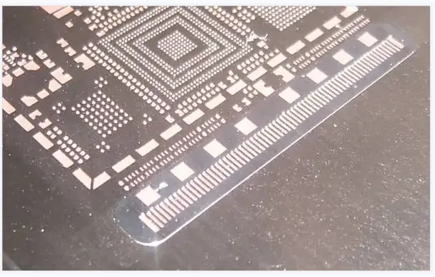
First of all, let's take a look at the expression form of steel stencil layer on CAM software:
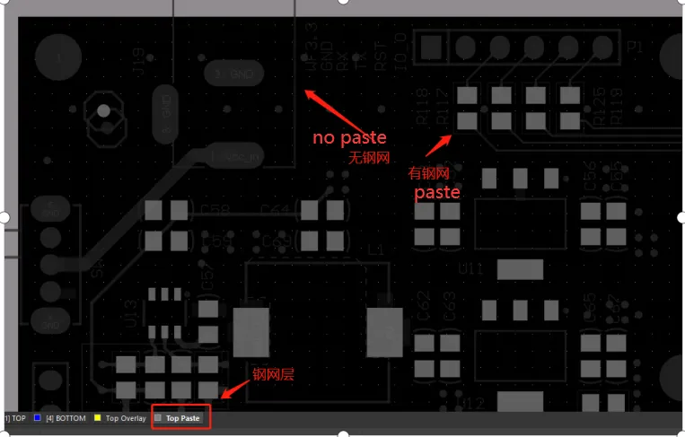
You will find that some devices in the steel stencil layer are steel mesh, some are not steel mesh, we carefully observe that there are steel stencil are patch devices, no steel stencil are plug-ins.
So what causes there to be no steel stencil in the in-line device? Did we miss it when we drew the package? In fact, it is not, we first understand the role of steel mesh, you know why only patch devices have steel mesh.
First of all, our PCB design needs to be produced in the board factory, and then it needs to be fabricated in the patch factory. The welding of the patch device is divided into the welding of the patch device and the welding of the in-line device. The technology used for these two types of devices is different, the surface patch device adopts reflow welding process, while the in-line device adopts wave soldering process
Reflow soldering: refers to the process of melting pre-coated solder paste (solder paste is usually composed of a mixture of tin powder and flux), so that it returns to a flowing liquid state (this process is reflux), so that pre-placed on the solder plate on the device and the solder in full contact to achieve the purpose of welding.
Wave crest welding: usually the welding surface is directly in contact with the solder after melting at high temperature to form a wave crest so as to achieve the purpose of welding.
After we understand the above information, we will find that reflow welding is to be coated with solder on the pad in advance, so the solder paste placed on the pad is sure to need tools, our steel stencil layer is used in welding to patch packaging pad solder paste, steel stencil refers to the corresponding position of the steel plate in the patch pad open holes, and then apply solder paste on the steel plate, The solder paste will fall into the pad from the hole, which is the role of our steel mesh, so our steel stencil layer in cam software is only in the patch device, which is why there is no steel stencil plug-in.
Then whether our steel stencil layer and solder resistance layer need to be expanded, in fact, this is not needed, external expansion is mainly for our solder resistance layer, the size of the steel stencil layer is needed and the size of the solder pad, so that we can accurately coated with solder.